
HDPE Pipe Pressure Testing Equipment: A 110 mm Laboratory Setup
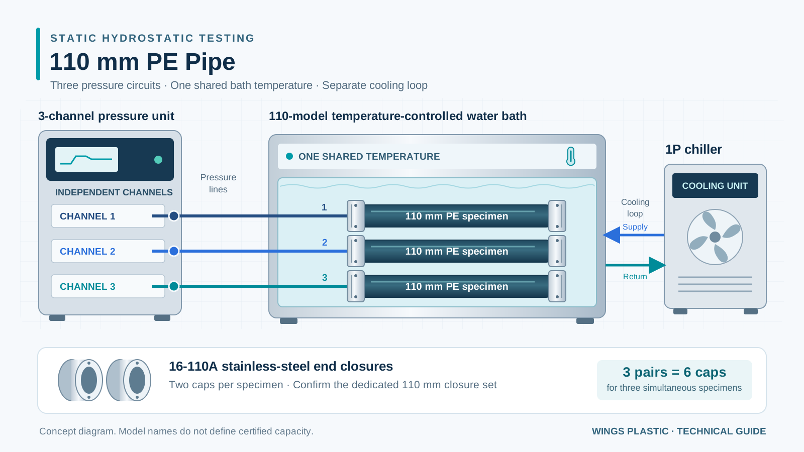
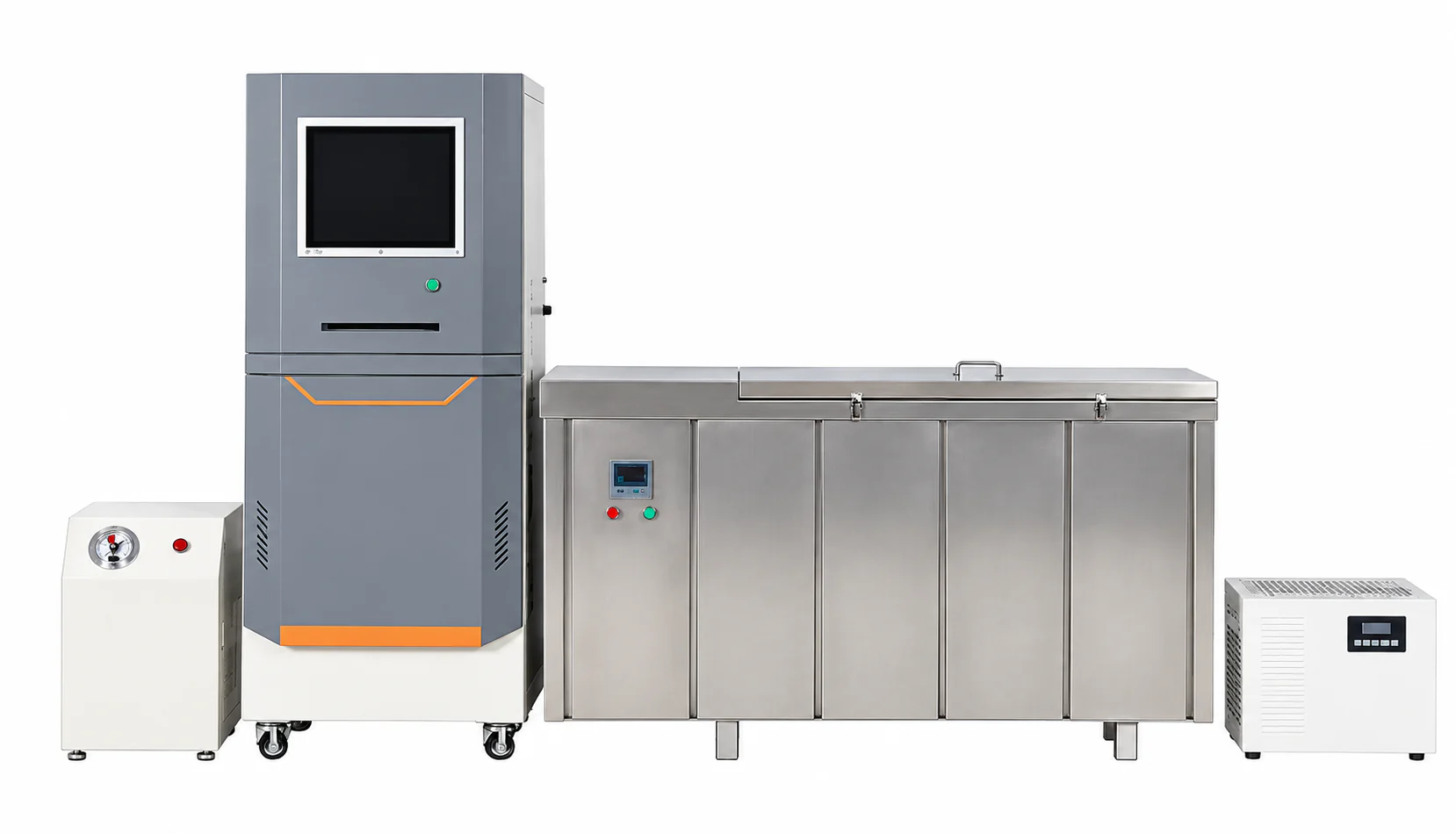
To check the internal-pressure resistance of HDPE pipe, a laboratory needs a hydrostatic pressure testing system that controls pressure, water temperature and test duration together. For 110 mm PE pipe, a practical equipment package comprises a three-channel pressure unit, a 110-model constant-temperature water bath, a 1P chiller and 16-110A stainless-steel end closures. This guide explains what each item does, how to specify a complete set and how the results relate to the pipe's pressure rating.
1. What Does a Hydrostatic Pressure Test Establish?
In a water-in-water test, the pipe specimen is filled with water, sealed at both ends, immersed in a controlled bath and subjected to a specified internal pressure. The laboratory records whether it survives the required period, or the time and mode of failure. ISO 1167-1 describes the general internal hydrostatic-pressure test method; ISO 1167-2 addresses pipe specimen preparation.
A hydrostatic tester does not assign a PN rating by itself. The declared pressure class depends on the material classification, pipe dimensions, design coefficient, application and governing product standard. A laboratory pressure test checks performance against a specified requirement.
| Term | What it describes | How to use it |
|---|---|---|
| PN / declared pressure class | A product designation tied to reference conditions and the applicable specification. | Check the pipe marking, material, SDR and product documentation. |
| Sustained hydrostatic test | Resistance to a specified internal pressure at a specified temperature over time. | Use the prescribed stress, duration, specimen count and acceptance rules. |
| Short-time hydraulic / burst test | Response to short-term pressurization under a defined method. | Use it only for the requirement it evaluates; do not convert burst pressure into a service rating. |
ASTM D1599 explicitly distinguishes short-time hydraulic results from long-term strength. A successful short burst test is therefore not a substitute for the sustained-pressure tests and other qualification checks required for PE pressure pipe.
Here, 110 mm refers to the pipe's nominal outside diameter. It does not identify a unique wall thickness or pressure class. For background, see our HDPE SDR guide and PE80 versus PE100 material guide.
2. A Complete Equipment Package for 110 mm PE Pipe
The following is the specified configuration for this 110 mm laboratory example. Model labels are purchasing identifiers: obtain the supplier's drawings and rated specifications before treating them as guaranteed capacities.
| Equipment | Quantity for this setup | Function | What to confirm |
|---|---|---|---|
| Three-channel pressure unit | 1 unit with 3 independently controlled channels | Pressurizes, holds and records each specimen's test. | Usable pressure range, independent isolation, control accuracy, timing and data export. |
| 110-model constant-temperature water bath | 1 bath | Conditions and immerses the capped pipe specimens at a common temperature. | Usable internal dimensions, water depth and clearance for all 3 assemblies. |
| 1P chiller | 1 matched cooling unit | Removes heat when the bath must operate below ambient temperature or reject excess heat. | Cooling capacity at the intended conditions, flow, connections and temperature limits. |
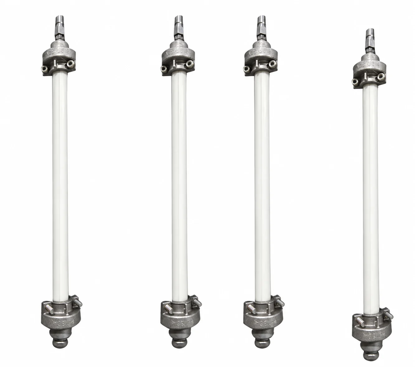
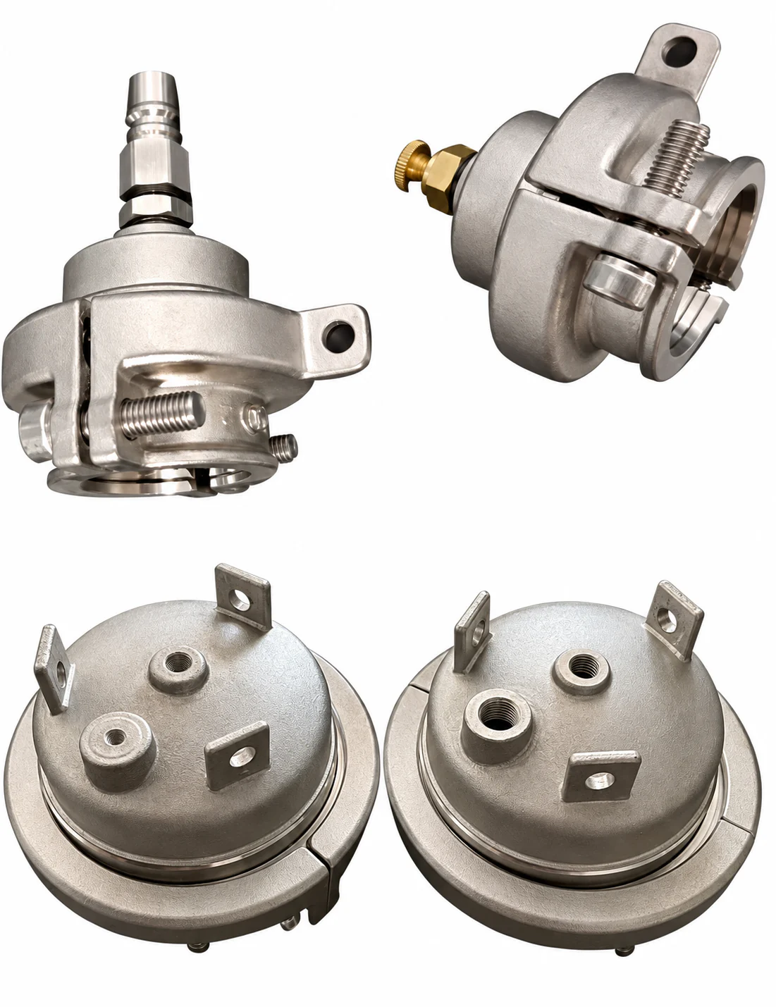
| 16-110A stainless-steel end closures | For 3 simultaneous 110 mm specimens: 3 matching pairs, or 6 end caps | Seal both ends and connect the specimens to the pressure system. | Actual 110 mm sealing/gripping parts, wall-range compatibility, load type and pressure/temperature rating. |
3. What the Three-Channel Pressure Unit Does
The main unit generates water pressure and regulates it as the pipe responds to the load. Each test channel needs its own measurement and control so a leak or failure on one specimen can be isolated. For this setup, plan one specimen per channel, with a separate pressure hose and identified test record.
- Independent operation: verify that each channel can be started, stopped and depressurized independently, with the other tests continuing within their permitted limits.
- Pressure capability: specify the required working range and accuracy at the actual test points. A high maximum pressure alone says little about control quality at lower pressures.
- Traceable data: require specimen ID, pressure history, time, interruption status and failure indications. Temperature must also be recorded, either through the same software or a synchronized bath logger.
- Long-duration operation: confirm what happens during power loss, pressure loss, water shortage and communication failure. An interrupted test needs a documented disposition under the chosen method.
Three pressure channels do not create three bath temperatures. With one undivided bath, all immersed specimens share one temperature. Different temperature programs must run sequentially or use separately controlled baths. The number of replicates is set by the test plan, not by the number of installed channels.
4. Matching the 110-Model Water Bath and 1P Chiller
110-model constant-temperature water bath
The bath combines a water tank, heater, circulation system, temperature sensor and controller. Circulation helps maintain a uniform environment around the specimens. The pressure unit controls water inside the pipe; the bath controls the surrounding water temperature.
The model name "110" must not be read as a 110-litre tank volume. Ask for usable length, width, depth and a loading drawing. Check the complete assembly: the required free pipe length, both end closures, hose connections, supports and clearance for water circulation. A bath that accepts one bare pipe may still be too small for three capped specimens.
For an extruded pipe specimen, the general free-length rule in ISO 1167-2:2006, clause 5.1.1 is at least three nominal diameters and at least 250 mm. For 110 mm pipe, max(3 × 110, 250) = 330 mm between the end caps. The cut specimen and the bath need additional space for the closure assemblies; 330 mm is not the total assembly length.
Bath selection by specimen dimensions and water depth follows the approach described by test-equipment manufacturer IPT. Temperature stability and spatial uniformity should be demonstrated under the intended load; a display resolution is not a calibration result.
1P chiller
A chiller removes heat from the bath circuit. It can be necessary for a low-temperature test when the room is warmer than the target water temperature. For example, a bath cannot hold 20 °C in a 30 °C room using a heater alone.
"1P" is a nominal equipment size, not a verified cooling capacity in kW. Ask for the cooling output at the required leaving-water and ambient temperatures, along with flow, pressure head, reservoir arrangement and permitted return-water temperature. A fixed conversion from 1P to cooling kW is not a sufficient sizing method.
Chiller manufacturer Cold Shot Chillers explains the distinction between motor horsepower and useful cooling output. For the purchased unit, use its rated cooling-performance data.
Confirm that the bath and chiller controllers operate together and that the supplier provides a suitable connection arrangement. If an elevated-temperature program is required, check whether the cooling loop must be isolated or bypassed. Do not circulate hot bath water through a chiller that is not rated to accept it.
Size the complete thermal system. Bath volume, ambient conditions, insulation, incoming water, specimen loading and the required pull-down time all affect cooling demand. The specified 1P unit remains subject to verification against that duty.
5. Specifying 16-110A Stainless-Steel End Closures
End closures, also called test end caps or fixtures, must both seal the pipe and withstand the forces generated during the test. They are not ordinary plumbing plugs. The requested 16-110A stainless-steel fixture series must include the correct parts for the actual 110 mm pipe.
Confirm whether "16-110A" denotes a size series, a supplied multi-size kit or one specific assembly. Do not assume that one pair fits every diameter from 16 to 110 mm. Ask for a parts list covering the actual pipe outside diameter, wall range, inserts, seals and pressure connections.
Manufacturers distinguish A-type and B-type closures and different sealing arrangements. For example, Jinjian's JJEC range lists A-type without tie rods and B-type with tie rods. Confirm the axial-load arrangement required by the test method; the "A" in a quotation must be checked against the supplier's drawing.
- Quantity: three simultaneously tested 110 mm pipe sections need three suitable pairs of end closures, not one 110 mm pair shared across three channels.
- Material and rating: obtain the stainless-steel grade and the permitted pressure/temperature envelope for the complete assembly, including seals, fasteners and connections.
- Pipe compatibility: check the actual outside diameter tolerance, SDR/wall thickness and the manufacturer's gripping and sealing method.
- Service parts: include replacement seals, the required mounting tools and the matching rated hoses/adapters in the quotation.
Leakage at a cap, fitting or hose must be investigated separately from a rupture in the pipe wall. Record where the leak occurred; do not label every pressure drop as a failed pipe.
6. How Is the Test Pressure Chosen?
Start with the applicable product specification and its test schedule. For PE water-supply pipe, ISO 4427-2 is a relevant product-standard reference. Water, gas and industrial pipe specifications are not interchangeable. Confirm the required material class, stress, temperature, duration and acceptance criteria before selecting the machine program.
The circumferential-stress relationship explains why outside diameter alone is insufficient:
p = 2 × σ × e / (d − e)
With p and σ in MPa and d and e in mm, the result p is in MPa. For the ISO 1167 pipe test, use the measured mean outside diameter for d and the minimum wall thickness within the free test length for e. Apply the governing method's measurement and rounding rules. Also, 1 MPa = 10 bar.
For a geometry-only example, take d = 110.0 mm and e = 10.0 mm. The equation gives p = 0.20 × σ. If an approved test schedule specified σ = 10.0 MPa, that geometry would give p = 2.0 MPa, or 20 bar. This assumed stress is an arithmetic example, not a prescribed PE100 test condition and not a PN assignment.
By contrast, calculating a declared service-pressure class uses the appropriate design stress and reference conditions. Substituting that service pressure for the laboratory setpoint would skip the test standard's stress requirement. Use the measured specimen dimensions and the selected test schedule together.
7. Laboratory Workflow and the Test Report
The equipment package supports the following workflow. The controlled laboratory procedure must supply the exact specimen dimensions, conditioning time, pressurization sequence, tolerances and failure rules.
Define the test
Record the standard and edition, pipe batch, material grade, nominal OD, SDR, test conditions and required replicates.
Prepare and measure
Prepare specimens and measure the required dimensions using calibrated equipment. Retain the free test length required by the method.
Fit, fill and condition
Install the correct closures according to their instructions, fill with water, remove trapped air and condition the assembly in the bath.
Control and record
Run the approved pressure program. Record each channel's pressure and time together with bath temperature and any interruption.
Inspect the outcome
After controlled depressurization, record survival or failure time, location and mode. Investigate closure leakage separately.
Release the report
Compare the recorded result with the specified acceptance criteria and retain calibration references, raw data and specimen traceability.
Use pressure-rated connections and suitable guarding, follow the supplier's mounting instructions, and verify zero pressure before loosening a cap or hose. The bath contains heated water during elevated-temperature tests. These are laboratory water-pressure tests; substituting compressed gas changes the stored-energy hazard and the method.
A useful report identifies the laboratory, operator, specimen/batch, measured dimensions, calculated setpoint, actual pressure and temperature histories, test duration, closure type, interruptions, outcome and governing acceptance rule. A machine screen showing "pass" without those conditions is insufficient evidence of conformity.
8. What to Put in the Purchase and Acceptance Checklist
| Check | Evidence to request |
|---|---|
| Three-channel independence | A demonstration that one channel can be isolated while the other two hold their required conditions. |
| 110 mm specimen loading | A dimensioned drawing showing three complete capped assemblies, hose clearances, supports and usable water depth. |
| Pressure and temperature performance | Calibration information and an acceptance run at the intended operating points, including bath uniformity under load. |
| 1P cooling suitability | Cooling-capacity data at the intended ambient/water conditions and a compatible bath/chiller connection diagram. |
| 16-110A closure supply | Three 110 mm pairs for three simultaneous specimens; confirm seals, inserts, fasteners, load arrangement and complete-assembly ratings. |
| Utilities and accessories | Separate electrical requirements for each item, water quality/supply, drainage, floor load, access space and rated hoses. |
| Test data and continuity | Sample exported report, raw-data access, time synchronization, interruption handling and recovery instructions. |
Also budget for specimen cutting/preparation, dimensional measuring tools and traceable reference instruments. Additional product tests may be required alongside hydrostatic testing; purchasing these four core items does not by itself equip a laboratory for every PE pipe certification requirement.
9. Frequently Asked Questions
Can this system test different PN classes of 110 mm pipe?
Potentially, provided the required pressure/temperature range, wall compatibility, closures and test method are covered. The diameter alone does not establish those requirements.
Can three channels test at 20, 60 and 80 degrees Celsius at the same time?
Not in one undivided water bath. Independent pressure control still shares a common bath temperature. Separate temperatures require separate controlled environments.
Is the 1P chiller always sufficient?
No. It is the specified starting size for this package; actual suitability depends on thermal load, ambient conditions, water temperature and pull-down requirements.
Does one set of 16-110A fixtures cover all three channels?
Check what the supplier means by a "set." If it contains only one 110 mm pair, it seals only one 110 mm specimen. This three-specimen arrangement needs three compatible pairs.
Does surviving a high pressure prove the pipe is PN16?
No. A result is meaningful only with its temperature, duration, specimen geometry and acceptance criteria. The declared pressure class also requires the applicable material and product-conformity basis.
10. Technical References and Image Notes
The links below support the test-method distinctions and equipment principles in this guide. The specified 110-model bath, 1P chiller and 16-110A fixture designation must be confirmed against the actual supplier's documentation; examples from other manufacturers do not establish their ratings.
- ISO 1167-1:2006 — general method for resistance to internal hydrostatic pressure.
- ISO 1167-2:2006 — preparation of pipe test pieces.
- ISO 4427-2:2019 — PE pipes for water supply and pressure drainage/sewerage.
- ASTM D1599 — short-time hydraulic pressure testing and the limitations of its results.
- IPT test baths — specimen-based bath sizing, circulation and temperature control.
- Jinjian JJEC end closures — manufacturer examples of closure types and sealing arrangements.
- Tianpeng hydrostatic test systems — examples of independently controlled channels, bath options and diameter-specific end closures.
Equipment and end-closure photographs: supplied reference images, retouched to remove scene backgrounds and overlaid marks. They illustrate general arrangements, not certified dimensions or model specifications. System diagram: original WingsPipeMachine explanatory illustration, not a certified assembly drawing. Technical references checked September 15, 2026.
Connect Pipe Production with Measurable Quality
Define the pipe grade, OD/SDR range, governing standard and laboratory test schedule alongside your extrusion-line requirements.
Explore the HDPE Pipe Extrusion Line