
HDPE Pipe Surface Quality: Melt, Die, Calibration and Cooling Control
A rough, grooved or wavy HDPE pipe surface is rarely solved by changing one temperature setpoint. Surface quality is the visible result of resin condition, melt homogeneity, die-wall stress, calibration, heat removal and line-speed stability. This guide provides a disciplined diagnostic sequence without presenting one supplier's process window as a universal recipe.
1. Define the Defect Before Adjusting the Line
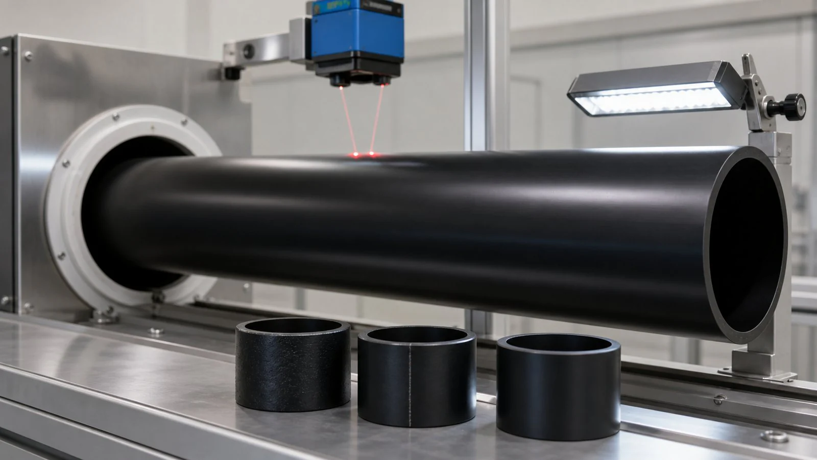
Use consistent lighting and record whether the mark is longitudinal, circumferential, periodic or random. Note whether it appears on the inner surface, outer surface or both. A defect that repeats once per haul-off revolution suggests a different mechanism from a continuous die line.
| Observed pattern | Likely process family | First evidence to collect |
|---|---|---|
| Fine roughness or sharkskin | High die-exit stress, melt temperature or die-lip condition | Actual melt temperature, output, die pressure and lip inspection |
| Continuous longitudinal line | Die contamination, damage or flow obstruction | Line position, die-lip cleanliness and tooling history |
| Periodic rings or waviness | Output, haul-off, vacuum or cooling oscillation | Cycle frequency compared with drives, pumps and puller rotation |
| Ovality or lower-side sag | Insufficient support, uneven calibration or heat removal | Pipe temperature profile, nozzle balance and calibrator alignment |
| Black specks or discolouration | Contamination or degraded residence material | Material lot, purge history, dead spots and screen condition |
2. Record a Process Baseline
Before making changes, capture the compound grade and lot, additive or stripe ratio, screw speed, gravimetric throughput, barrel and die setpoints, measured melt temperature, head pressure, line speed, vacuum level, water supply and return temperatures, pump pressure and ambient conditions. Photograph the defect and mark its circumferential position.
Change one variable at a time. Simultaneously increasing melt temperature, vacuum and haul-off speed may hide the original cause and create a second defect. Allow the line to reach a new steady state before judging the response.
3. Melt Preparation and Temperature
Barrel setpoints are inputs, not proof of melt condition. Screw work, back pressure, output and residence time all contribute to the actual melt temperature and homogeneity. Compare measured melt temperature and motor load with the compound supplier's processing guidance.
- Under-plasticized or poorly mixed melt can produce a dull, uneven surface and unstable pressure.
- Excessive temperature or residence time can promote oxidation, odour, discolouration and deposits that later detach as specks.
- Contaminated feed can create streaks or inclusions even when the thermal profile is correct.
- Moisture handling should follow compound-supplier guidance. PE is not treated like a hygroscopic engineering polymer, so drying is not a universal requirement; wet pellets or condensation still must not enter the process.
Published values such as 200–230 °C can be plausible for some pipe compounds and line conditions, but they are not universal setpoints. Grade, screw design, colour system, output and measurement location matter.
4. Die Geometry, Cleanliness and Exit Stress
Sharkskin and melt fracture originate at the die exit when surface stress exceeds what the melt can relax smoothly. Corrective trials may include reducing output, reviewing the die-lip temperature, checking land length and gap, or using a qualified processing aid. The appropriate action depends on the compound and tooling.
A sharp longitudinal line usually justifies stopping for a die-lip inspection rather than compensating with vacuum. Clean tooling with an approved method; avoid scratching the land or lip. Confirm mandrel centring through measured wall distribution, not visual judgement alone.
5. Calibration and Vacuum
The calibration sleeve establishes outside geometry while initial cooling creates enough skin strength for the pipe to travel downstream. Vacuum must be stable and sufficient for the diameter, melt strength and calibrator design, but “more vacuum” is not automatically better. Excessive vacuum or local water imbalance can mark the surface and increase drag.
- Check the sleeve for deposits, blocked passages, wear and concentric alignment.
- Verify vacuum stability at the tank, not only the controller setpoint.
- Inspect entry-water distribution and sealing conditions around the hot pipe.
- Relate surface marks to sleeve slots, holes or support contact before changing the die.
6. Cooling Should Remove Heat Without Distorting the Pipe
Cooling demand increases with mass flow, wall thickness and incoming melt temperature. Initial sizing and later bulk cooling have different jobs. Water temperature, flow, nozzle pattern and tank length must therefore be selected as a system.
Very aggressive one-sided cooling can lock in uneven shrinkage; insufficient or poorly balanced cooling can produce sag, ovality and dimensional drift. There is no universal cooling-water temperature or mandatory tank-exit surface temperature for every HDPE pipe. Establish the operating window from the pipe size, compound, line speed, plant-water conditions and dimensional results.
7. Output and Haul-Off Stability
Wall mass is governed by the relationship between melt output and line speed. A changing output/haul-off ratio produces wall variation even if outside diameter remains constrained by the calibrator. Trend extruder throughput, melt pressure and haul-off speed together.
Periodic diameter variation can come from drive oscillation, inconsistent feeding, vacuum cycling, pump behaviour or non-uniform puller contact. Frequency analysis is useful: compare the pitch of a surface pattern with screw rotation, puller belt revolution and pump-control cycles.
8. Evidence-Based Troubleshooting Matrix
| Defect | Checks | Controlled trial |
|---|---|---|
| Outer-surface roughness | Melt homogeneity, die stress, calibrator water and sleeve deposits | Make one small supplier-approved thermal or output change, then compare at steady state |
| Inner-surface roughness | Mandrel temperature, internal deposits, residence time and melt fracture | Verify melt condition and tooling cleanliness before changing downstream settings |
| Longitudinal groove | Fixed circumferential position, lip damage, contamination or sleeve contact | Inspect and clean the corresponding tooling location |
| Periodic rings | Pattern pitch against drive, feeder, pump and vacuum cycles | Stabilize the identified oscillating subsystem |
| Ovality | Cooling balance, support, puller pressure and measurement timing | Balance water and support first; verify dimensions after specified conditioning |
| Black specks | Material contamination, screen, dead zones and shutdown history | Isolate the material lot and execute an approved purge/cleaning procedure |
9. Inspection and Applicable Standards
Appearance, outside diameter, wall thickness, ovality and conditioning rules must come from the governing product specification and customer requirements. Do not apply a universal ±0.5% OD or ±5% wall tolerance to every size and standard.
ISO 4427-1:2019 covers the general aspects of PE piping systems for water supply and pressure drainage/sewerage and makes clear that the purchaser or specifier selects the applicable requirements. Hydrostatic resistance is evaluated with methods such as ISO 1167-1. The contract may instead reference another regional standard, which must control the inspection plan.
10. Frequently Asked Questions
What melt temperature should an HDPE pipe line use?
Use the qualified compound supplier's processing range and verify actual melt condition. A universal website value cannot account for screw design, output, colour, residence time or measurement location.
Will increasing vacuum remove every surface defect?
No. Vacuum corrects a sizing relationship; it cannot remove die contamination or melt fracture and can create drag or marking if excessive.
How often should dimensions be checked?
Set a frequency in the quality plan based on the governing standard, process capability, risk and customer requirements. Continuous gauges do not replace calibrated offline verification.
Plan a Stable HDPE Pipe Process
Share the compound, pipe standard, OD/SDR range, output target and available cooling-water conditions so extrusion, calibration, cooling and haul-off can be evaluated together.
Review the HDPE Pipe Extrusion Line